IEIndustrial Automation & Embedded
IoT Scalable Smart Automation System
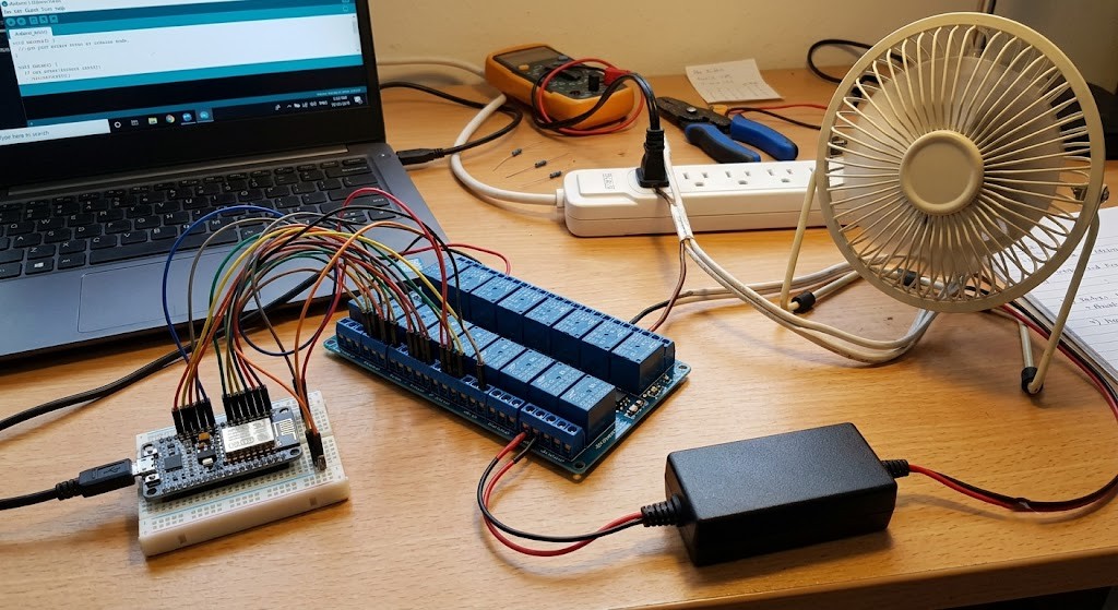
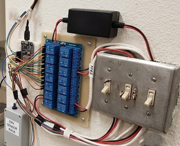
A localized IoT network — a NodeMCU (ESP8266) edge controller driving a 16-channel opto-isolated relay module to safely switch high-voltage appliances and lab equipment, with PIR/LDR smart-lighting energy optimization and a custom MIT App Inventor Android dashboard.
Hardware & Architecture
- NodeMCU ESP8266 edge controller acting as a local web server and GPIO manager.
- 16-channel 5V relay module with optocoupler isolation to safely toggle high-voltage loads.
- PIR occupancy sensor + LDR ambient-light sensor for the smart-lighting subsystem.
- Dedicated external 5V/3A PSU to drive 16 relay coils without browning out the MCU.
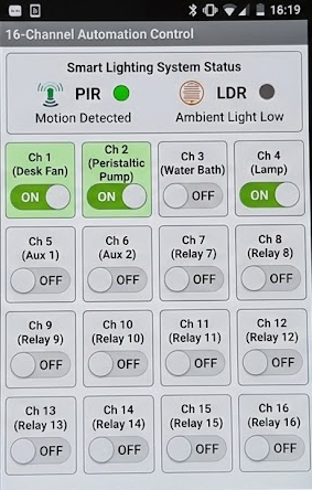
- Custom Android app (MIT App Inventor) issuing HTTP GET requests to the NodeMCU API.
Key Highlights
- REST-style endpoints toggle individual relays and expose a JSON /status feed for the app to mirror hardware state.
- Autonomous smart-lighting loop turns lab lights on only when it's dark AND motion is detected, off otherwise, to save energy.
- Polling app UI updates button colors every 2s to stay in sync with the relays.
Images
Code
iot_automation.inoESP8266 Web Server + Smart Lightingcpp
#include <ESP8266WiFi.h>
#include <ESP8266WebServer.h>

// --- Network Configuration ---
const char* ssid = "YOUR_WIFI_SSID";
const char* password = "YOUR_WIFI_PASSWORD";

// --- Hardware Pins ---
// Array to hold the GPIO pins connected to the 16-channel relay
// Note: ESP8266 has limited GPIO. For 16 channels, I/O expanders
// (two 74HC595 shift registers or an MCP23017 via I2C) are industry standard.
// This code assumes an I2C expander is used for scalability, but
// simplifies the logic for demonstration.
const int relayPins[16] = { /* Insert your specific expanded/multiplexed pins here */ };

// Smart Lighting Sensors
const int pirPin = 12; // D6 - Motion Sensor
const int ldrPin = A0; // Analog LDR Sensor
const int smartLightRelayIndex = 0; // Assign Relay 1 to the Smart Light

ESP8266WebServer server(80);

// Relay state array (Active LOW for most relay modules)
bool relayStates[16];

void setup() {
  Serial.begin(115200);
  // Initialize Relays to OFF (HIGH)
  for (int i = 0; i < 16; i++) {
    pinMode(relayPins[i], OUTPUT);
    digitalWrite(relayPins[i], HIGH);
    relayStates[i] = false;
  }
  pinMode(pirPin, INPUT);

  // Connect to Wi-Fi
  WiFi.begin(ssid, password);
  Serial.print("Connecting to WiFi");
  while (WiFi.status() != WL_CONNECTED) {
    delay(500);
    Serial.print(".");
  }
  Serial.println("\nConnected! IP: " + WiFi.localIP().toString());

  // --- Define API Endpoints ---
  // Toggle a specific relay: e.g., http://<IP>/toggle?relay=3&state=1
  server.on("/toggle", HTTP_GET, []() {
    if (server.hasArg("relay") && server.hasArg("state")) {
      int relayNum = server.arg("relay").toInt();
      int state = server.arg("state").toInt();
      if (relayNum >= 0 && relayNum < 16) {
        // Relays are active low
        digitalWrite(relayPins[relayNum], state ? LOW : HIGH);
        relayStates[relayNum] = state;
        server.send(200, "text/plain", "Relay " + String(relayNum) + " set to " + String(state));
      } else {
        server.send(400, "text/plain", "Invalid Relay Number");
      }
    } else {
      server.send(400, "text/plain", "Missing Arguments");
    }
  });

  // Get all states for App UI updating
  server.on("/status", HTTP_GET, []() {
    String json = "{";
    for (int i = 0; i < 16; i++) {
      json += "\"" + String(i) + "\":" + String(relayStates[i]);
      if (i < 15) json += ",";
    }
    json += "}";
    server.send(200, "application/json", json);
  });

  server.begin();
}

void loop() {
  server.handleClient();
  handleSmartLighting();
}

// --- Smart Lighting Logic (Energy Optimization) ---
void handleSmartLighting() {
  int lightLevel = analogRead(ldrPin);
  bool motionDetected = digitalRead(pirPin);
  // Thresholds: Dark environment AND motion detected
  if (lightLevel < 400 && motionDetected) {
    // Turn ON light
    digitalWrite(relayPins[smartLightRelayIndex], LOW);
    relayStates[smartLightRelayIndex] = true;
  } else if (!motionDetected) {
    // Turn OFF light to save energy
    digitalWrite(relayPins[smartLightRelayIndex], HIGH);
    relayStates[smartLightRelayIndex] = false;
  }
}app_inventor_notes.txtMIT App Inventor Architecture (Mobile UI)text
UI Layout Components
--------------------
1. Web Component (Web1): Sends HTTP requests to the NodeMCU.
2. Clock Component (Clock1): Fires every 2000ms to poll /status and update
   button colors (Green = ON, Gray = OFF).
3. Buttons (Btn_Relay1 .. Btn_Relay16): Arranged in a scrollable Table Arrangement.

Logic Blocks (pseudo-code)
--------------------------
1. Global Variables:
   - NodeMCU_IP: "http://192.168.1.xxx"

2. Button Click (example, Relay 1):
   When Btn_Relay1.Click:
     If Relay1_State is ON  -> set Web1.Url = join(NodeMCU_IP, "/toggle?relay=0&state=0")
     If Relay1_State is OFF -> set Web1.Url = join(NodeMCU_IP, "/toggle?relay=0&state=1")
     call Web1.Get

3. Status Sync:
   When Clock1.Timer:
     set Web1.Url = join(NodeMCU_IP, "/status")
     call Web1.Get
   When Web1.GotText:
     parse JSON response
     loop keys 0..15
     update background colors of Btn_Relay1 .. Btn_Relay16 from the boolean values
     so the app matches the actual hardware state.